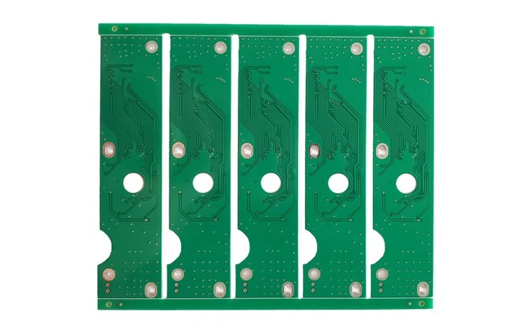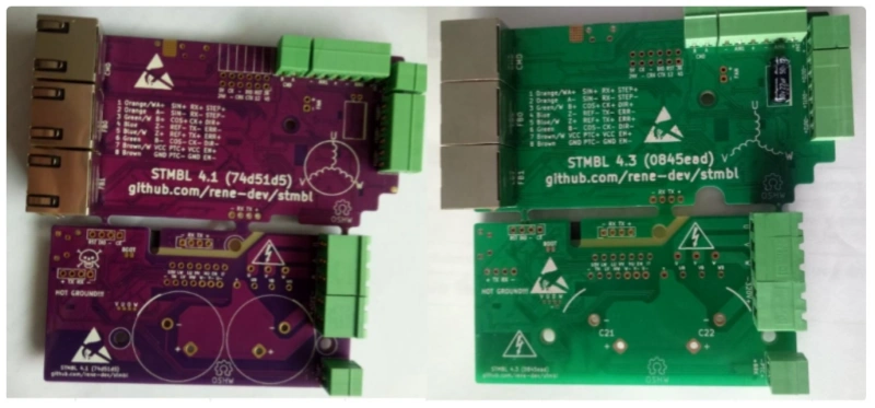
The STMBL is a well-known, open-source 3-phase servo drive hardware and software project suitable for motors up to 2.2kW for driving brushless DC (BLDC) and permanent magnet synchronous motors (PMSMs). It’s particularly famous in the DIY CNC, robotics, and automation communities. As a professional PCB and PCBA manufacturer assembly factory,I’m honor to participate in full PCB manufacture and assembly for STMBL4.1 and STMBL4.3 projects with Mr. Rene.
Servo Motor Drive Preparation
Components & Tools
As an open-source project,a successful assembly of the Servo Motor Drive begins with gathering all necessary documentation about STMBL Getting Started Guide,PCB and Pinout of connector components and tools. The following list outlines the essential items required for the process:
- C143 capacitor (22µF, 6.3mm diameter)
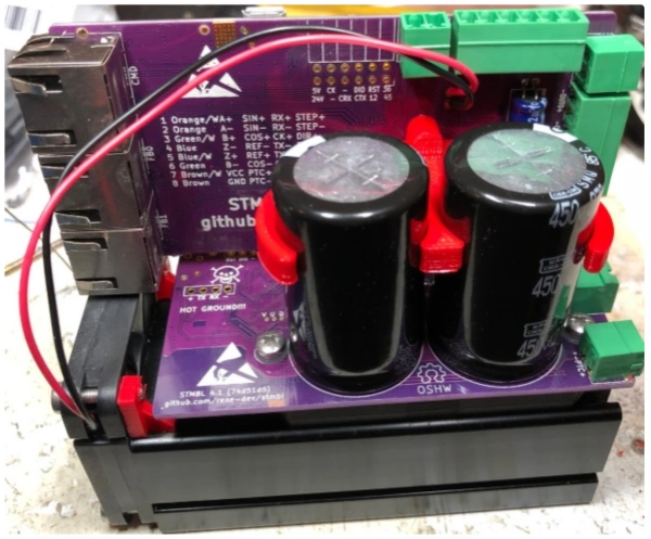
- C21 and C22 capacitors (270µF, 400/450V)
- Insulated washers and screws for isolation
- 3D printed standoffs for the IRAM module
- IRAM256 module
- Soldering iron and solder
- 3D printed fan mounts and fan
- Right-angle header
- Steady-bracket with self-tapping screw
- Fan wires
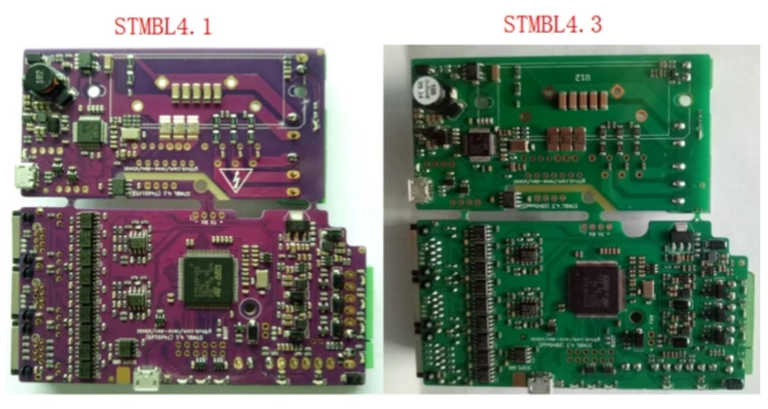
DIY Version from STMBL4.0 to STMBL4.0 and STMBL4.3
This is a classic and rewarding project in the DIY CNC and motion control community from Mr. Rene. The transition from STMBL4.0 to STMBL4.1 and STMBL4.3.This involves replacing the power/driver section of your setup while keeping your existing STM32F4 Discovery board and likely your power supply and motor.
- What You’ll Need:
- STMBL4.3 Power/Driver Board Kit (or components to assemble one).
- Your existing STM32F4 Discovery Board.
- A new 5-pin cable to connect the Discovery board to the 4.3 driver (the pinout changes).
- Basic tools: Soldering iron, multimeter, screwdrivers, etc.
- Step-by-Step Upgrade Process:
- Preparation and Safety:
- Backup your config: Connect to your current STMBL4.0 via the web interface and save your configuration file (
config.json). This contains all your motor tuning parameters, which you can re-use. - Disconnect all power: Mains, DC Bus, everything.
- Backup your config: Connect to your current STMBL4.0 via the web interface and save your configuration file (
- Disassemble the Old System:
- Carefully disconnect all wires from your STMBL4.0 board: Motor phases (U, V, W), DC Bus (+,-), Encoder, and the cable to the STM32F4 Discovery.
- Unscrew and remove the old STMBL4.0 board.
- Assemble the New STMBL4.3 Board:
- If you have a kit, solder all the components onto the new v4.3 driver board. Pay close attention to the orientation of IGBTs, diodes, and capacitors.
- Critical Step: Solder the 5-pin header (or a connector) for the link to the STM32F4 Discovery board.
- Install the New Board:
- Mount the new STMBL4.3 board in your enclosure. It may have a different footprint, so you might need to drill new mounting holes.
- Use thermal paste and properly mount the IGBTs to the heatsink. This is crucial for thermal performance.
- Rewiring:
- Power: Connect the DC Bus (+ and -) to the new board. The terminals are likely similar.
- Motor: Connect the motor phases (U, V, W).
- Encoder: Connect the encoder cable to the same connector on the STM32F4 Discovery board. This part doesn’t change.
- Control Link: This is the key change. Connect the new 5-pin cable between the STM32F4 Discovery and the new 5-pin header on the STMBL4.3 board.
- !CAUTION! The pinout is different from v4.0. Do not use the old cable. Refer to the official STMBL4.3 schematics for the correct pin-to-pin connection. Incorrect wiring will destroy the board.
- Software and Configuration:
- The STM32F4 Discovery board now needs new firmware to communicate correctly with the v4.3 driver.
- Download the latest
stmblsource code from the GitHub repository. You need the version that supports the v4.3 comms protocol. - Compile and flash the new firmware to your STM32F4 Discovery board. The build configuration for a v4.3 drive will be different (e.g.,
make F4DISC_rev4_3). - After flashing, power on the system and connect via the web interface.
- Commissioning:
- The motor should now be detected.
- You can upload your old
config.json. The basic motor parameters (pole pairs, encoder resolution) will work, but you must re-tune the current loops and PIDs because the electrical characteristics of the driver are completely different. - Start with very low current limits and follow the official STMBL tuning procedure.
- Preparation and Safety:
Testing & Firmware
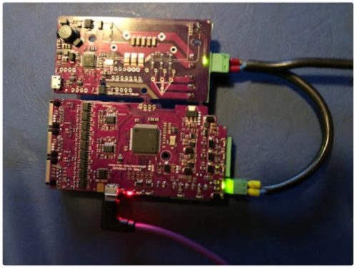
Board Power-Up
After assembling the main components, technicians should prepare for the initial power-up. Connect the Servo Motor Drive to a stable power supply. Double-check all wiring and ensure that no conductive objects rest on the board. Activate the power supply and observe the board’s indicator LEDs. These lights confirm that the board receives power and that the voltage levels remain within safe limits. If the LEDs do not illuminate, disconnect the power immediately and inspect all connections.
Firmware Flashing
The next step involves flashing the latest firmware onto the Servo Motor Drive. Use a USB connection to link the board to a computer. Install the required libusb driver, as this software is essential for DFU mode flashing. Many users overlook this step because the standard installer does not include libusb. Select the correct firmware file for the board revision. Incorrect firmware selection often leads to flashing failures or non-responsive hardware. Follow the manufacturer’s instructions for the flashing process. Wait for the confirmation message before disconnecting the board.
Troubleshooting
Technicians may encounter several common issues during initial testing and firmware flashing. The table below summarizes the most frequently reported problems and their details:
| Issue Description | Details |
| No channel 6 servo (rudder) movement | Users reported issues with servo movement during initial testing. |
| Need for libusb installation | Installation of libusb is required for DFU mode flashing, which is not included in MP’s installer. |
| Incorrect firmware selection | Selecting the wrong firmware can lead to flashing failures. |
| Challenges with servo movement | Users experienced difficulties in getting the servo to respond correctly during testing. |
For additional support, several online community resources offer reliable troubleshooting guidance:
- Comprehensive troubleshooting guides for servo motor drives
- Testing procedures after repairs to ensure proper operation
- Practical solutions for common and advanced errors
- Systematic approaches to diagnosing servo motor problems
- Emphasis on regular maintenance and performance factors
Tip: Always consult community forums and official documentation when facing persistent issues. These resources often provide step-by-step solutions and updated repair instructions.
Component Installation
Capacitors & IRAM
Proper installation of capacitors and the IRAM module ensures the reliability and longevity of the Servo Motor Drive. Technicians should follow these steps for optimal placement and orientation:
- Place capacitors in areas free from corrosive gases, steam, and excessive vibration. This precaution prevents premature failure and maintains performance.
- Shield outdoor capacitors from direct sunlight. Exposure to sunlight can degrade materials and reduce lifespan.
- Maintain an ambient temperature near 40°C for all capacitor installations. High temperatures accelerate aging and may cause malfunction.
- When stacking high-voltage capacitors, limit the arrangement to three layers without horizontal spacers. Spacers between layers help dissipate heat and prevent overheating.
- Ensure a minimum distance of 10 centimeters between the outer shells of high-voltage capacitors. This spacing reduces the risk of electrical arcing.
- Use individual flexible conductors for each capacitor connected to the busbar. This practice avoids mechanical stress on porcelain bushings and prevents cracking.
- Secure the IRAM module using 3D printed standoffs and insulated washers. Proper isolation protects sensitive electronics from electrical shorts and vibration.
Note: Careful attention to placement and spacing during installation reduces the risk of component failure and improves overall system stability.
Fan Mounting
Efficient cooling is essential for the Servo Motor Drive to operate safely under load. Technicians should consider several best practices when mounting fans:
- PWM control allows precise adjustment of fan speed based on real-time temperature. This method improves cooling efficiency and reduces noise.
- Voltage control changes fan speed by altering voltage. While simple, this approach may increase noise during high-demand operation.
- Thermal sensors automatically regulate fan speed according to component temperature. This automation enhances reliability and reduces the need for manual intervention.
- Manual control provides flexibility for systems without automated cooling. Operators can adjust fan speed in response to changing conditions.
Secure the fan using 3D printed mounts and ensure unobstructed airflow across heat-sensitive components. Route fan wires neatly to prevent interference with other parts. Confirm that the fan orientation matches the intended airflow direction for maximum cooling.
Tip: Regularly inspect fans for dust buildup and mechanical wear. Clean or replace fans as needed to maintain optimal performance.
Juottaminen
Soldering remains a critical step in assembling the Servo Motor Drive. Technicians must avoid common mistakes to ensure strong electrical connections and reliable operation. The most frequent soldering errors include:
- Bridging between pads, which can create electrical shorts and damage components.
- De-wetting solders, often caused by improper solder paste or insufficient heat, leading to weak joints.
- Poor wetting with lead-free solder, resulting in unreliable connections and potential compliance issues.
- Component shifting and tombstoning, typically due to temperature mismatches during the soldering process.
To minimize these risks, technicians should use a clean, temperature-controlled soldering iron and high-quality solder. They should inspect each joint for smooth, shiny surfaces and rework any dull or cracked connections. Proper technique and attention to detail during soldering prevent costly rework and system failures.
Caution: Always allow the board to cool before handling after soldering. Inspect all joints under magnification to catch hidden defects.
Final Assembly & Verification
Enclosure & Wiring
Technicians begin the final assembly by mounting the completed board and components into the enclosure. They must align the board with the standoffs and secure it using the provided screws. Proper mechanical assembly prevents vibration and accidental movement during operation. All wiring should follow the manufacturer’s layout, with cables routed neatly to avoid crossing power and signal lines. This practice reduces electromagnetic interference and simplifies future maintenance.
Before connecting any wires, technicians should review the wiring diagram and double-check each connection point. They must ensure that all connectors are fully seated and that insulation covers all exposed conductors. Using cable ties or wire ducts helps organize the wiring and prevents accidental shorts. Technicians should also label each wire for easy identification during troubleshooting or upgrades.
Tip: Neat wiring not only improves safety but also makes future diagnostics much easier.
Power Connections
Establishing reliable power connections is essential for safe and stable operation. Technicians should select shielded cables with the correct number of wires and ground them securely to minimize electrical noise. Surge suppressors protect the system from transient electromagnetic interference, especially when working with inductive loads. Proper transformer sizing ensures that the power supply can handle the total load without overheating.
The table below summarizes best practices for connecting power to the system:
| Best Practice | Kuvaus |
| Cable Selection and Shielding | Use shielded cables with the correct number of wires, securely grounded to minimize electrical noise. |
| Surge Suppression | Implement surge suppressors to guard against transient EMI generated by inductive loads. |
| Transformer Sizing | Calculate the required transformer rating by adding all power requirements and choose the closest standard rating above that. |
| Mounting, Bonding, Grounding | Properly bond and ground all components to reduce EMI and ground noise. |
Before powering up the Servo Motor Drive, technicians must perform several safety checks. The following table outlines the most important steps:
| Safety Check | Kuvaus |
| Power Disconnection | Ensure the power source is disconnected for 5 minutes before wiring to prevent accidental power on. |
| Wiring Sequence | Verify that the wiring sequence is correct to avoid short-circuits and equipment damage. |
| Grounding | Confirm that the DC power supply ground is accessible to prevent electrocution risks. |
| Temperature Caution | Avoid touching the motor due to high operating temperatures to prevent burns. |
Note: Never rush the power connection process. Careful verification at this stage prevents costly mistakes and ensures user safety.
System Check
After completing the mechanical assembly and wiring, technicians must verify system functionality before full operation. The following steps provide a systematic approach to checking the Servo Motor Drive:
- Connect the encoder to the drive according to the manufacturer’s instructions.
- Power on the system and observe for encoder-related error messages.
- Configure the drive settings as described in the manual, adjusting parameters such as “Speed Control Mode.”
- Rotate the potentiometer and toggle “Servo On” to activate the motor.
- Switch to “Position Control Mode” and connect the motion control card.
- Verify the motor rotation and output speed against the specified parameters.
- Fine-tune the I/O functions by adjusting the motion control card and testing outputs with onboard LED arrays.
Technicians rely on several diagnostic tools during system checks. The table below lists the most effective tools and their uses:
| Työkalun nimi | Kuvaus |
| Multi-Meters | Measure voltage, current, and resistance; essential for servo repair. |
| Meg-ohm Meter | Test insulation quality; important for ensuring motor safety during repairs. |
| Oscilloscopes | Observe waveforms and timing; crucial for analyzing motor performance. |
| Variable Speed Motor Test Stand | Back drives the motor for testing; necessary for brushless units to verify operational parameters. |
| Encoder / Resolver Test Equipment | Test pulse counts and relationships; essential for accurate motor positioning. |
| Servo Motor Drive Amplifiers | Allow for test running of motors post-repair; check dynamic operation and overall condition. |
| Signal Breakout Boxes | Provide access to feedback signals safely; simplify testing with an oscilloscope. |
⚡ Always use the correct diagnostic tool for each test. Accurate measurements and careful observation help identify issues before they become serious problems.
Technicians should document all test results and confirm that the system meets the required specifications. Only after passing all checks should the Servo Motor Drive enter regular operation.
Technicians who assemble the STMBL Servo Motor Drive should follow each step carefully and verify every connection. Community forums and official documentation provide valuable troubleshooting support. Maintaining a checklist for future maintenance and upgrades helps ensure long-term reliability. The table below highlights essential maintenance tasks for the STMBL Servo Motor Drive:
| Maintenance Task | Kuvaus |
| Regular Cleaning and Dust Removal | Keeps air vents and components clean to prevent overheating and electrical breakdowns. |
| Check Wiring and Connections | Ensures all cables remain intact and properly connected. |
| Monitor Temperature and Cooling System | Protects components by ensuring cooling systems function correctly. |
| Update Firmware and Software Regularly | Keeps the system current with performance improvements and fixes. |
| Oil Moving Parts | Lubricates servo motors for smooth operation. |
| Run Diagnostic Tests Periodically | Detects issues early using built-in diagnostics. |
| Replace Worn-out Components | Extends drive life by replacing parts like capacitors and fuses. |
| Follow Key Safe Maintenance Tips | Maintains electrical stability and protects the power system. |
| Perform Load Testing | Confirms the drive can handle rated loads safely. |
FAQ
What motors work with the STMBL Servo Drive?
The STMBL Servo Drive supports both AC and DC servo motors. Users can connect motors with a wide range of voltage and current ratings. Compatibility with various feedback systems ensures flexibility for different automation projects.
How can users update the firmware safely?
Always disconnect power before updating firmware.
Users should connect the board via USB, install the required libusb driver, and select the correct firmware file. Following the official flashing instructions prevents errors and protects the hardware.
What should users do if the board does not power up?
- Check all wiring and connections.
- Inspect indicator LEDs for activity.
- Remove power immediately if no lights appear.
- Review the assembly for shorts or loose components.
Can you make full PCB of STMBL4.1 and STMBL4.3?
Yes,we have all PCB files of STMBL4.1 and STMBL4.3 from Mr. Rene,and we can produce and assembly STMBL sevo drive boards for you after you get Mr. Rene’s permission.