Take apart a phone, a laptop, or a router and you will often find rigid green boards inside. If you cut the edge, you can see what looks like “stacked layers.” The core base material used in most of those boards is FR-4. FR-4 is the most common PCB base material in electronics. It appears in consumer devices, industrial control equipment, home appliances, and more. Globally, FR-4 makes up over 70% of the PCB base material market each year. This article breaks down what FR-4 really is and how to choose it.
What FR-4 Means
First, make one thing clear: FR-4 is not the name of a single formula or product. It is a flame-retardant base material standard set by NEMA (the National Electrical Manufacturers Association) in the United States. FR-4 stands for “Flame Retardant, Type 4.” According to the NEMA LI 1-1998 standard, any material that is a glass-fiber-reinforced epoxy resin and that passes the UL94 V-0 vertical burn test can be called FR-4.
The key point in this standard is flame retardancy. “FR” means the sample stops burning within 10 seconds after the flame is removed and it does not produce flaming droplets that ignite the cotton placed below the sample. The “4” is the level number. Lower levels such as FR-1 (phenolic paper) and FR-2 (epoxy paper) have poorer flame resistance and higher moisture absorption (>8%). Those now appear rarely in mainstream electronics and are mostly only found in very low-cost toys or simple boards.
Core Composition — A Composite of Glass Cloth and Epoxy Resin
At its core, FR-4 is a composite material. It is made mainly of two parts, similar to “rebar plus concrete” in a building. The materials are pressed and cured under heat and pressure. Typical processing conditions are 170–190°C and 20–30 kg/cm² pressure, with cure times usually from 60 to 90 minutes.
Glass Fiber Cloth (the Reinforcement)
The glass cloth acts as the structural frame. It makes up about 55%–65% of the base material by weight. The common type is E-glass (electrical glass). Typical E-glass contains 54%–56% silicon dioxide (SiO₂) and alkali metal oxides below 0.8%. E-glass gives good mechanical strength and dimensional stability.
High-end FR-4 may use S-glass (high strength glass). S-glass offers roughly 30% higher tensile strength than E-glass, but it raises cost by over 50%.
Weaving density of the cloth is described as warp × weft. For example:
- 7628 cloth: warp 46 threads/inch, weft 38 threads/inch — commonly used as multilayer core material.
- 2116 cloth: warp 76/inch, weft 68/inch — used for thinner base laminates.
This composite structure allows FR-4 to withstand drilling at speeds above 10,000 rpm in PCB production. Minimum drilled hole diameter can reach 0.1 mm.
Epoxy Resin (the Matrix and Binder)
Epoxy resin is the binder and matrix. It accounts for about 35%–45% of the base material by weight. The resin molecules generally contain two epoxy groups. When cured with amine-based hardeners, they form a three-dimensional network. Typical cure shrinkage is only 1%–2%, much lower than polyester resins (5%–8%).
Electronic-grade epoxies are often bisphenol A type. They have high volume resistivity (≥10¹⁴ Ω·cm), which provides strong electrical insulation between circuits on the board and helps prevent leakage and short circuits. Epoxy also resists acids, bases, and many organic solvents. After 1,000 hours in 85°C/85% RH aging, the insulation resistance usually remains at least 70% of its initial value.
Key Properties — Balanced Performance and Cost (Parameter Table)
FR-4 is a general-purpose choice because it balances many properties well. Below is a typical parameter table comparing ordinary FR-4, high-Tg FR-4, and halogen-free FR-4. Test standards listed are the common industry references.
| Property | Ordinary FR-4 (E-glass) | High-Tg FR-4 (E-glass) | Halogen-Free FR-4 (E-glass) | Test Standard |
|---|---|---|---|---|
| Dielectric constant (εr) @ 1 GHz | 4.5 ± 0.2 | 4.4 ± 0.2 | 4.6 ± 0.2 | IPC-TM-650 2.5.5.5 |
| Dissipation factor (tan δ) @ 1 GHz | 0.02 ± 0.003 | 0.018 ± 0.002 | 0.022 ± 0.003 | IPC-TM-650 2.5.5.5 |
| Glass transition temperature (Tg) | 130–150 °C | 170–200 °C | 140–160 °C | IPC-TM-650 2.4.25 |
| Continuous use temperature | ≤ 105 °C | ≤ 125 °C | ≤ 110 °C | IEC 60216-1 |
| Thermal decomposition (Td) | ≥ 340 °C | ≥ 360 °C | ≥ 350 °C | IPC-TM-650 2.4.31 |
| Flexural strength (room temp) | ≥ 150 MPa (longitudinal) | ≥ 160 MPa (longitudinal) | ≥ 145 MPa (longitudinal) | IPC-TM-650 2.4.4 |
| Tensile strength | ≥ 200 MPa | ≥ 220 MPa | ≥ 190 MPa | IPC-TM-650 2.4.1 |
| Flame retardant rating | UL94 V-0 | UL94 V-0 | UL94 V-0 | UL94 |
| Moisture absorption (24 h / 23 °C) | ≤ 0.15% | ≤ 0.12% | ≤ 0.18% | IPC-TM-650 2.6.2 |
| Volume resistivity | ≥ 10¹⁴ Ω·cm | ≥ 10¹⁵ Ω·cm | ≥ 10¹⁴ Ω·cm | IPC-TM-650 2.5.17 |
| Price (CNY / m²) | 80–120 | 150–200 | 180–240 | Market data |
From the table, high-Tg FR-4 offers better thermal resistance and lower dielectric loss. Halogen-free FR-4 is better for environmental compliance, but has somewhat higher cost. These parameters affect PCB manufacturing and reliability. For example, only high-Tg FR-4 with Tg ≥ 170 °C can reliably pass lead-free soldering profiles with peak temperatures around 260 °C.
Common Types — Grouped by Performance and Appearance
FR-4 is classified in many ways. The common classifications discussed in electronics forums include:
By Performance
- Ordinary FR-4: Tg 130–150 °C, medium dielectric loss. Used in normal temperature (0–60 °C), low-frequency (≤5 GHz) scenarios such as set-top box or router signal layers.
- High-Tg FR-4: Tg 170–200 °C, about 30% better thermal stability. Used in high-temperature environments such as near engines or heavy industrial zones. Common choice for automotive ECU boards.
- High-speed FR-4: Modified epoxy formulas that bring tan δ at 1 GHz below 0.015. Suitable for 1–10 GHz mid-to-high frequency boards, such as mid-band boards in cellular base stations. Cost is typically 20%–30% higher than ordinary FR-4.
By Environmental Standard
- Halogen-containing FR-4: Uses brominated epoxy for flame retardancy. Good flame performance, but burning releases HBr and other toxic gases. Not compliant with many modern environmental rules and is being phased out.
- Halogen-free FR-4: Uses phosphorus-based flame retardants. Chlorine and bromine content each ≤ 900 ppm, total halogens ≤ 1500 ppm. Burning produces far less toxic gas. This type is mainstream for consumer electronics.
By Appearance
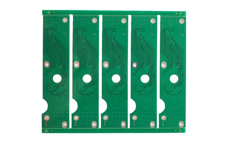
Solder mask color determines the visible board color. The resin itself is usually light yellow. Common solder mask colors:
- Green (over 80% of boards)
- Blue (common in medical devices)
- Black (military or anti-glare applications)
- White (LED boards to improve reflectivity)
Color does not change core material properties.
Main Applications — FR-4 as the Electronics Foundation
FR-4’s balance of performance and cost makes it widely used across many fields:
Consumer Electronics
Ordinary FR-4 is used for low-frequency signal layers (for example, circuits around baseband chips, I2C lines with frequencies ≤100 MHz) and power management PCBs in laptops. In practice, many small power boards use ordinary FR-4 without issues. For example, some power boards in entry-level phones run at 40–50 °C during normal use with stable performance.
Industrial Control
Devices like variable frequency drives and PLCs use FR-4. For higher temperature or harsher environments, high-Tg FR-4 is preferred. Siemens S7-200 PLC I/O boards, for instance, often use Tg 170 °C material to keep stable across −20 to 70 °C.
Home Appliances
Control boards in refrigerators and washing machines have low signal frequencies (≤50 MHz). Ordinary FR-4 gives the best cost-performance ratio. Large OEMs can reduce procurement costs by about 15% when using ordinary FR-4 in mass-produced boards.
Insulation Components
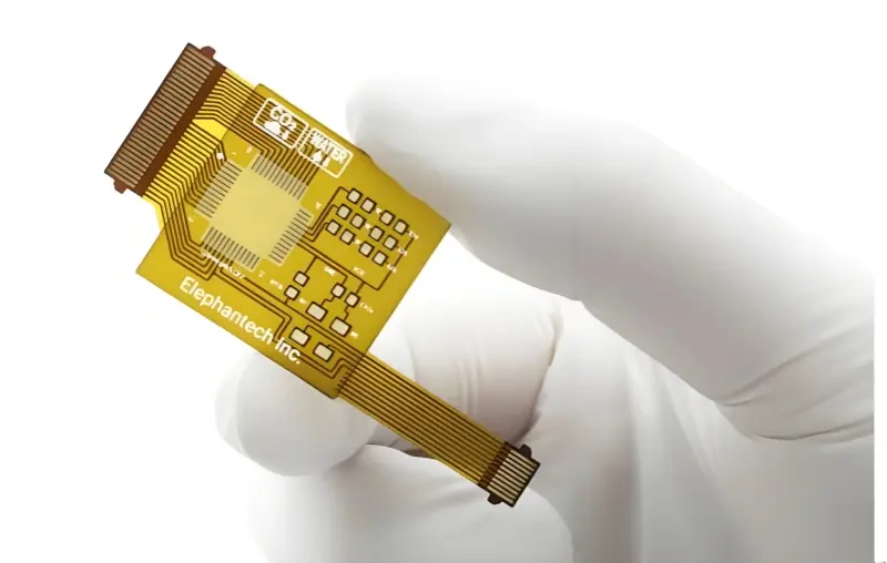
FR-4 is used for stiffening flexible circuits (FPC stiffeners), transformer insulation boards (with required temperature ≥ 105 °C), and motor insulation parts where volume resistivity ≥ 10¹⁴ Ω·cm is needed.
How FR-4 Compares to Other Common Base Materials (Comparison Table)
FR-4 is very versatile, but special cases require other materials. Below is a comparison often used in engineering selection.
| Base material | εr @ 1 GHz | tan δ @ 1 GHz | Tg (°C) | Cost (relative to FR-4) | Core advantage | Typical use |
|---|---|---|---|---|---|---|
| Ordinary FR-4 | 4.5 ± 0.2 | 0.02 ± 0.003 | 130–150 | 1× | Cost-effective, mature process | Appliance control, low-end routers |
| High-Tg FR-4 | 4.4 ± 0.2 | 0.018 ± 0.002 | 170–200 | 1.5–2× | High thermal stability | Automotive ECU, industrial drives |
| Rogers 4350B | 3.48 ± 0.05 | 0.0037 ± 0.0002 | 170 | 8–10× | Extremely low high-frequency loss, stable impedance | 5G RF boards, microwave antennas |
| Nelco N4000-13 | 3.65 ± 0.05 | 0.0045 ± 0.0003 | 210 | 6–8× | High Tg, low loss | Data center 25 Gbps Ethernet boards |
| FR-5 | 4.6 ± 0.2 | 0.02 ± 0.003 | 170 | 1.2–1.5× | Better moisture resistance than FR-4 | Humid environment devices |
| Polyimide (PI) | 3.5 ± 0.2 | 0.008 ± 0.001 | 260 | 10–12× | Flexible, very high temp | Wearables, aerospace flex circuits |
From this table:
- For very high frequencies (>10 GHz), Rogers 4350B has much lower loss. Its tan δ is about one-fifth of FR-4, reducing attenuation and maintaining impedance.
- For very high temperatures (>125 °C), polyimide’s Tg around 260 °C is superior.
- For humid or wet environments, FR-5 has lower moisture absorption and may be more reliable.
Test results often show that at 25 GHz, FR-4 signal loss can reach 0.8 dB/in, while Rogers 4350B may show only 0.15 dB/in.
Limitations — When Not to Use FR-4
FR-4 is not universal. The common limitations and the scenarios that call for other materials are:
- Poor performance at high frequencies: Above 5 GHz, tan δ tends to rise with frequency. At 5 GHz tan δ may reach ~0.025, at 10 GHz ~0.03, and at 25 GHz ~0.04. Signal attenuation becomes large. For Massive MIMO antenna boards working around 24–30 GHz, FR-4 can cut transmission distance by more than half, so Rogers materials are required.
- Dielectric stability under temperature variation: With temperature swings between −40 and 85 °C, ordinary FR-4 dielectric constant can vary by about ±5%. That can cause impedance shifts beyond allowed tolerances for high-speed memory like DDR5 (impedance tolerance ±5%). Tests show FR-4 impedance drift up to 12% in extreme cold, while some high-performance materials show only 3% drift.
- Limited moisture resistance: Ordinary FR-4 can lose dielectric strength after 500 hours at 85 °C / 85% RH, with degradation ~30%. That makes it unsuitable for long-term submerged or highly wet applications.
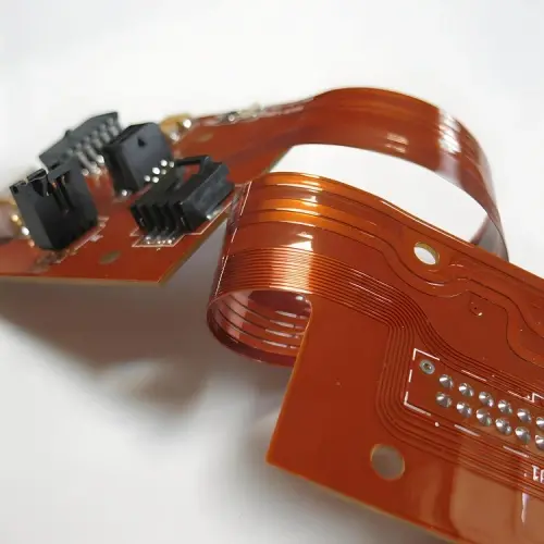
- Low flexibility: FR-4 is rigid. It will break if bent to a radius less than about 50 mm. For flexible or foldable devices (smartwatches, foldable phones), polyimide or flexible copper-clad laminates are the right choices.
Simple Decision Flow for Selecting PCB Base Material
Follow this quick checklist:
- Is the use frequency > 5 GHz?
- Yes → consider high-speed FR-4, Nelco N4000-13, or Rogers.
- No → go to next question.
- Is operating temperature > 125 °C?
- Yes → consider PI or high-Tg materials.
- No → next question.
- Is flexibility needed?
- Yes → choose PI or flexible substrates.
- No → next question.
- Is the environment very humid or underwater?
- Yes → consider FR-5 or specialized waterproof materials.
- No → next question.
- Do you need strict environmental compliance (low halogens)?
- Yes → choose halogen-free FR-4.
- No → ordinary FR-4 may be fine.
In short: for ordinary low-frequency, normal-temperature applications choose ordinary FR-4. For higher thermal stress use high-Tg FR-4. For mid-to-high frequency boards use low-loss FR-4 or special laminates. For extreme high frequency or precision RF, use Rogers or similar.
Conclusion
FR-4 became the standard base material in electronics because it balances flame retardancy, mechanical strength, electrical insulation, and low cost. It supports a wide range of devices—from cheap appliance control boards to important industrial PCBs. Yet FR-4 is not the best for every case. High-frequency, high-temperature, flexible, or underwater applications often need specialty materials.
As engineers say: “There is no single best material. There is only the material that best matches the requirements.” Match the electrical, thermal, mechanical, and cost constraints, and then pick the base material that fits. That is the right way to choose between FR-4 and the many other options available.